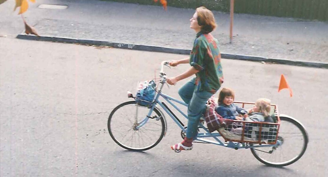
8Freight Cargo bike - restoration / project

Helicoil time:
Cheers to @novocaine for the tip...

The rear derailleur hanger was bent and the threads were stripped.
I started by bending it back into shape, it worked, I don't like doing an operation like this on what I think is cast ally, but needs must.
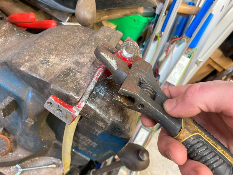
a1.jpg
Then on to drilling out the stripped hole and threading it with the tap from the kit. (the kit was £10.5 on fleabay.)
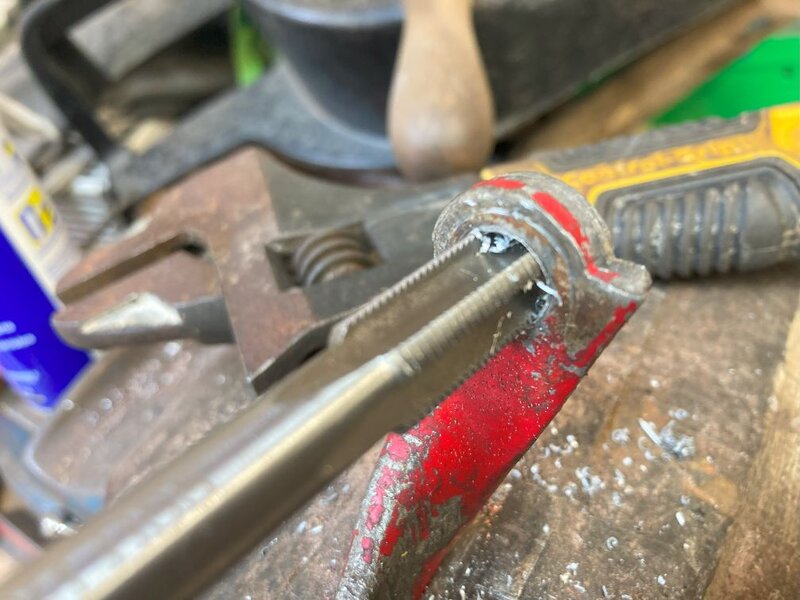
a2.jpg
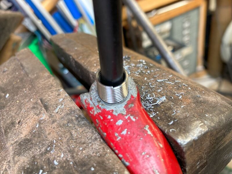
Inserting the coil is easy, but takes a bit of skill, I only know this because I did it wrong the first time and one of the coil threads spanned across 2 of the cut threads, I just happened to notice this so it was ok, and because it was a through hole I could just thread it on to remove it and try again.
a3.jpg
a4.jpg
a5.jpg
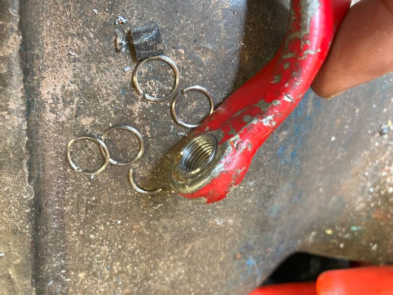
The coil is too long for this application, so I cut the excess off with a side cutters one ring at at time. seemed to work.

a6.jpg
a7.jpg
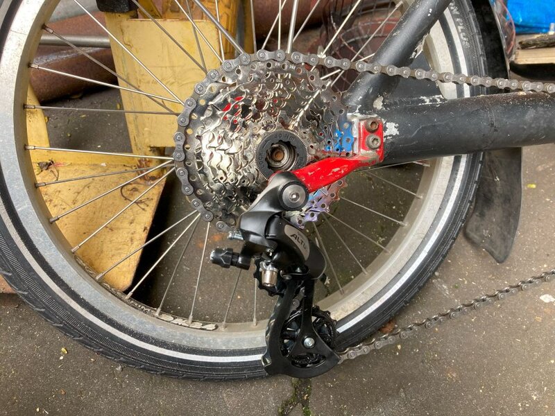
Back on the bike, the enormous sprocket wouldn't fit, I think Joe may have said something similar previously. So I just removed the meat off the mount block with an angle grinder and a bit of freehand and jobs a throbber.
a8.jpg
I had the rear sprocket cluster and the derailleur in stock from buying a few bits when chain reaction were selling off all their bits a while ago. So I might as well use them, 3 new chains from Joe and these parts make an almost new transmission. Just the front chainwheel is pre-loved.
Next post will be the chain idler, or mid drive jockey, or whatever you would call it. I wonder if Burrows made a user manual for this bike. I saw a manual or guide for the Ratcatcher on ebay, it may still be there, If someone has a scan of an 8 freight manual maybe send me a message. @mynchiboy ?
 
Lathe time:
b1.jpg
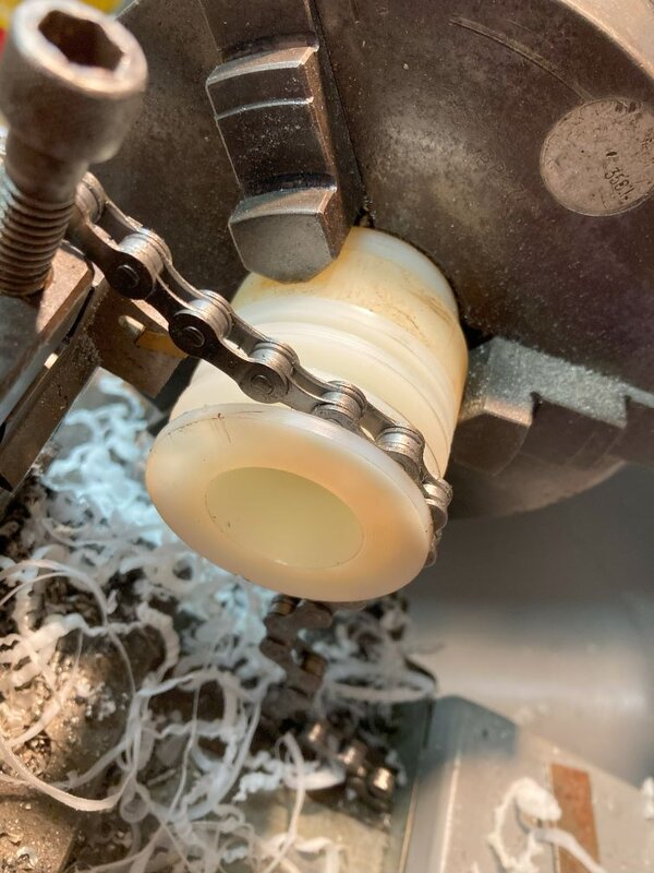
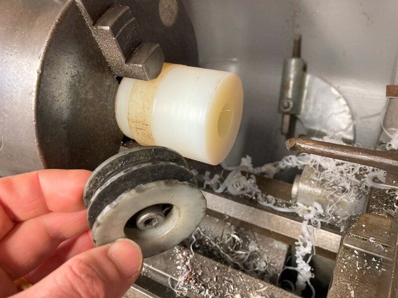
Make the blank in the rear look like the roughed up piece of plastic in the front that I pulled from the orange 8 freight. ( the yellow 8 freight has a blue wheel!

b2.jpg
I spun it in the lathe and gouged metal points into it until it looked like the above and a chain would fit in the groove. There is some more nuance to my process, but not much. On the old one from the other bike there was one bearing held in with a circlip. I happened to have 2 old bearings in a box that would do it albeit a different size so I worked around that and a stud that would thread into the m8 hole in the mount point.
I had to get the chain to clear the bottom of the front load basket bar, see photos further on so a good guess gave me 1 1/2 inches of an internal diameter for the pulley so I made it a little bit bigger.
b5.jpg
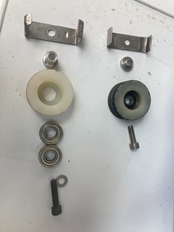
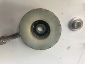
the line up on the left is the new one, and on the right the original from the orange bike.
The bent piece of stainless steel at the top of the photo stops the chain going missing. (sometimes) then the little plug is a spacer and bush between the bearing inner and the threads of the screw. You can get screws specially to fit bearings with machined sides and the length and thread you want but I was using what I had so rather than spend pennies I spent hours on the lathe working on aluminium to make that little bush. My skill on the lathe is somewhat limited, but I have both a lathe and some time so I might as well go at it. The lathe is an ancient Harrison and gets zero points for accuracy, but at this level of machining it seems to do the trick!
b6.jpg
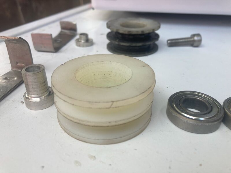
Another view, I think I used imperial bearings, so I really just cut a bit on the lathe and then checked fit. So giving sizes would be fairly pointless, as I wouldn't have followed them anyway, but suffice to say that the white bit is about 2" round and 1" high and the chain fits in the grooves.
b7.jpg
Burrows used a circlip to hold the bearing in, I can't really see why. The screw holds it all together. So I didn't fit a circlip.
b8.jpg
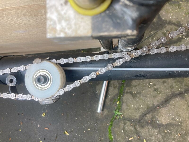
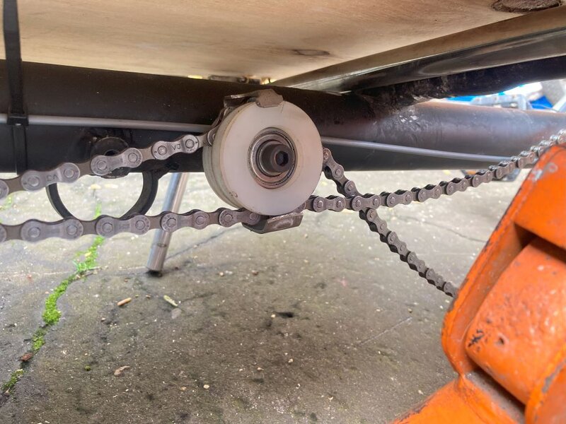
This is how it should look, with the driving chain (going under the pulley) clearing the bar to the right in the photo.
But after running the chain it looked like this:
b9.jpg
It would appear that there is an element in the design that I didn't understand. the slack end of the chain needs to have a wide enough gap in the white idler pulley to slide quite freely, so I widened the groove in the lathe. The driving side doesn't matter so much. But as the photo above shows, the chain gets stuck and then all chaos breaks loose, luckily the situation was short lived!

I put an ancient thumb shifter on the handlebars, I have struggled to get my selection of mixed crap old shifter to index correctly with new back ends, so I can't be bothered. I am quite happy to have an old shimano friction thumby and do my own indexing. There is a relatively big chainwheel on the front and a huge range on the back so in the flatlands where I live there is ample range, I think the rear block is 11-36 and the front is 46t. I think this range is greater than what I have on the orange one. and it can take a full load up the steepest railway bridge approach, but not leave you spinning when going downhill empty.

I think the last bit I will tackle is the gas strut and actuator for the stand. I have fitted a 1000N strut that @mynchiboy gave me, but I think it is too strong. the ones on the other bikes are 400n. The yellow bike's stand just stays up by itself and then a little lever actuated by a thumbshifter on the handlebars pushes the stand down and then the gas strut follows through. on the orange bike the gas strut and gravity are always trying to push the stand down, but it is held up by a tiny little stainless locking mechanism with a carbon fibre feather spring. a brake lever on the handlebar unclips the lock and the stand falls. The black bike, being the subject of this thread, has the cable routing mount for the orange bike type, but not the other bits. It has a different stand than both. but it looks original. So I am not sure what way it should be. This would all make more sense with photos. so Maybe my next post will have some!

Cheers!
 
Good work on the restoration.
I remember the chain running on an o-ring in a small grove cut in the centre of the pulley?
Don't recall the function: centre the chain? noise reduction? dunno?
 
Helicoil time:
Cheers to @novocaine for the tip...

The rear derailleur hanger was bent and the threads were stripped.
I started by bending it back into shape, it worked, I don't like doing an operation like this on what I think is cast ally, but needs must.
View attachment 841662
Then on to drilling out the stripped hole and threading it with the tap from the kit. (the kit was £10.5 on fleabay.)
View attachment 841663
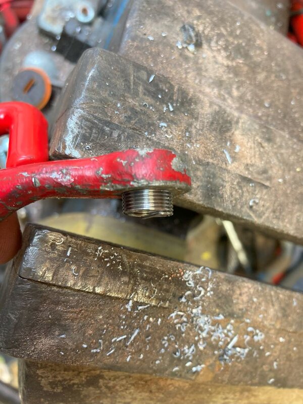
Inserting the coil is easy, but takes a bit of skill, I only know this because I did it wrong the first time and one of the coil threads spanned across 2 of the cut threads, I just happened to notice this so it was ok, and because it was a through hole I could just thread it on to remove it and try again.
View attachment 841664
View attachment 841665
View attachment 841666
The coil is too long for this application, so I cut the excess off with a side cutters one ring at at time. seemed to work.
View attachment 841667
View attachment 841668
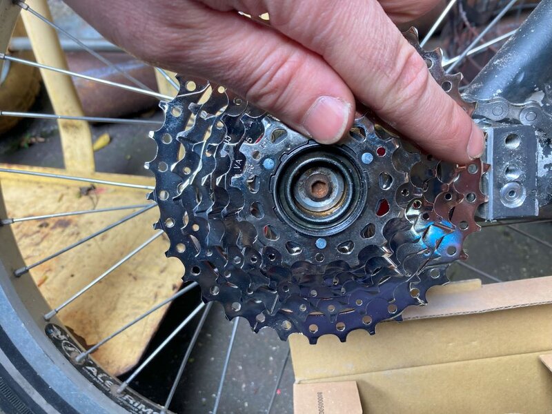
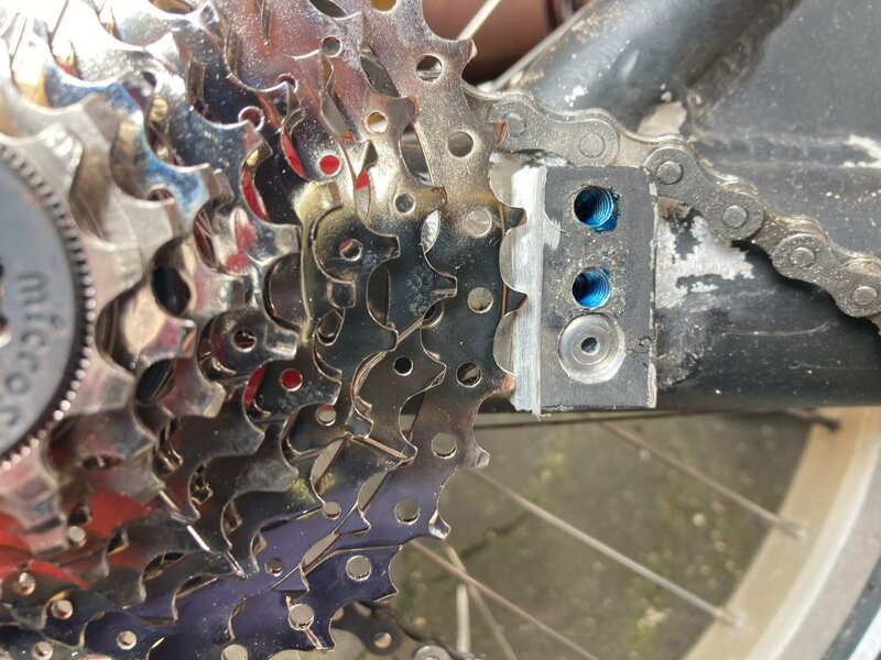
Back on the bike, the enormous sprocket wouldn't fit, I think Joe may have said something similar previously. So I just removed the meat off the mount block with an angle grinder and a bit of freehand and jobs a throbber.
View attachment 841669
I had the rear sprocket cluster and the derailleur in stock from buying a few bits when chain reaction were selling off all their bits a while ago. So I might as well use them, 3 new chains from Joe and these parts make an almost new transmission. Just the front chainwheel is pre-loved.
Next post will be the chain idler, or mid drive jockey, or whatever you would call it. I wonder if Burrows made a user manual for this bike. I saw a manual or guide for the Ratcatcher on ebay, it may still be there, If someone has a scan of an 8 freight manual maybe send me a message. @mynchiboy ?
Nice work. I'd say you were lucky not have that hanger snap though. I did similar with a brake caliper and CRACK!
 
The lathe is an ancient Harrison and gets zero points for accuracy
Excellent work! I could see you’ve got an old-style tool holder so I was going to ask you what lathe you had! I disagree about the accuracy bit. I learned on ancient Harrisons and Colchesters in the 90s and they were just fine. Everything is adjustable on those. And if there is a bit of slack you just work with the backlash 👍
 
Excellent work! I could see you’ve got an old-style tool holder so I was going to ask you what lathe you had! I disagree about the accuracy bit. I learned on ancient Harrisons and Colchesters in the 90s and they were just fine. Everything is adjustable on those. And if there is a bit of slack you just work with the backlash 👍
Still run a Boxford AUD. Yer it's not new, it takes a bit of time for accuracy these days but its still doable.
 
So,,, on to the stand quick action.
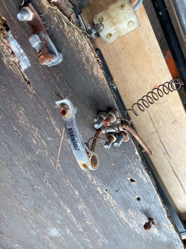
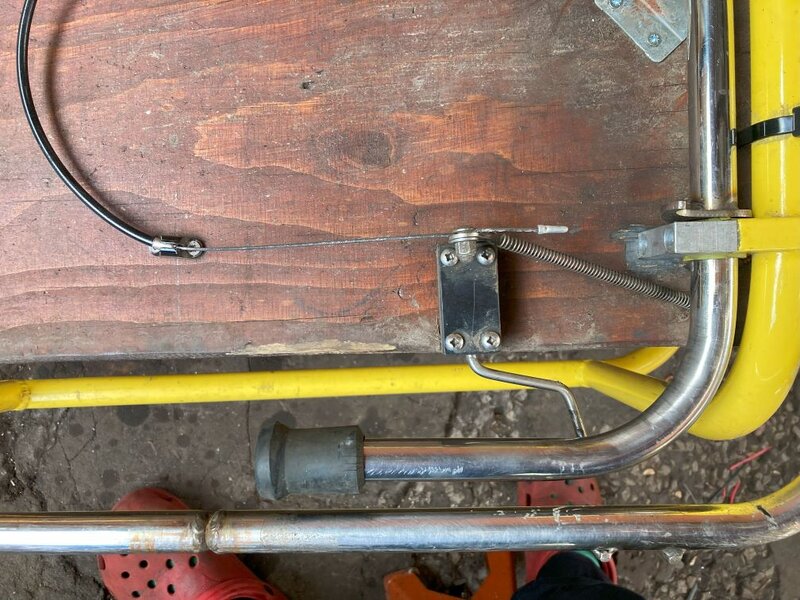
This was on the underside of the wooden cargo plate.
6c.jpg
It was a bodge to make something out of bike spares, (QR skewer, brake screws) that looks like this one on the yellow bike:
3d.jpg
Hopefully it is clear that the bike is upside down and that this is the yellow bike, front to right, The little black box is basically just a bushing made of two halves of plastic that hold the s shaped piece of 5mm stainless bar. it has a cam at the cable end. the cam action is about 1". the cable pulls the cam and the rod turns, effectively kicking the stand downwards, or upwards as it would be in the photo, or towards your face if you are viewing this on a mobile phone. This operation is actuated by a repurposed gear lever on the handlebars. Once kicked the gas strut takes over and the stand drops.
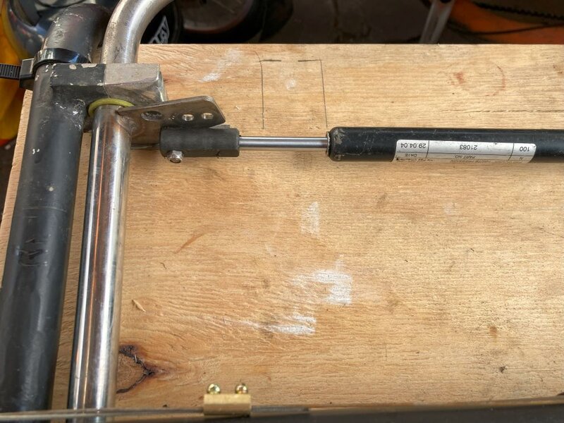
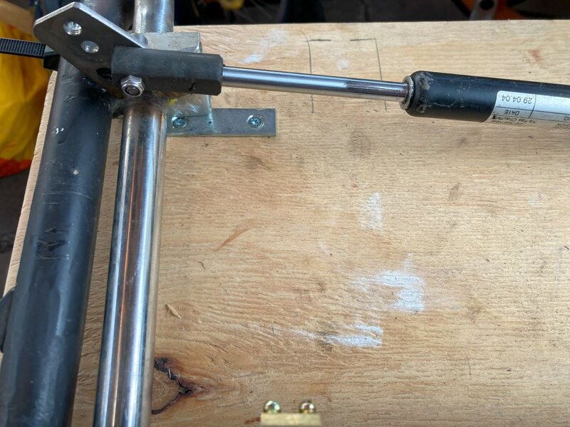
1d.jpg

2d.jpg
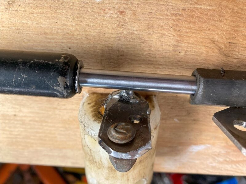
the two photos above are my mods to the stand, I had to drill one hole to move the location of the gas strut so it can push the stand the full way out. this is not the original strut from this bike. I have screwed on a little plate where the cam strike the wood, to protect the wood and to hold the stand at the right point. It is just a bit of mending plate. So it is a bit of a bodge. But it works now if it is kicked so all I had to do is make up a thing like on the yellow bike.
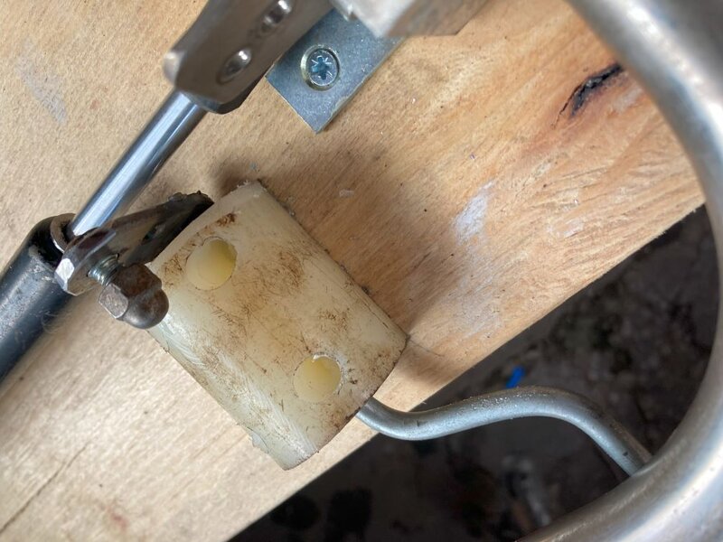
4d.jpg
so this is my effort, a bit of 40mm plastic with a slice off it to give it a flat surface, freehand I bored a wonky hole through it and then 4 screw mount holes. I bent up a bit of 6mm mild steel, because that is what I had to hand and what I can easily weld, and I welded on the cam lever on the end, so it is locked into place, unlike the one on the yellow bike which could be disassembled. I did it this way because I was too lazy to cut the block in half and bore it afterwards. I welded it in situ, setting the plastic on fire momentarily. Dinner called so it is up to this point now and I will add some cable tomorrow and hopefully it will work.
5d.jpg

My welding is just two spots with the little old lidl arc welder. Great value for 17 years at £50 or whatever it was. Still going for odd jobs.
It is hardly elegant, but it is just to get the bike going and for it to be ready for use occasionally as a second or third backup bike. No plans to sell it or scrap it, so I just want it to work. I could have left this part out, and just kicked it manually, but somehow my ocd couldn't let that happen.
I suspect that I'll finish this and make a video for YT to wrap this project up.
 
Excellent work! I could see you’ve got an old-style tool holder so I was going to ask you what lathe you had! I disagree about the accuracy bit. I learned on ancient Harrisons and Colchesters in the 90s and they were just fine. Everything is adjustable on those. And if there is a bit of slack you just work with the backlash 👍
This is a Harrison 11", a bit of a big brute. Oh to have had it when it was new. it is metric, but it has been hammered in a school. it has the fancier gearbox but someone has blanked off the 3 knobs, so it is basically a big workhorse for straightforward turning by feel rather than accuracy, so far it has worked for me. It is adjustable and I have had the whole thing apart and attempted to adjust it, but it is loose where there was wear and binds where there wasn't, so it is what it is.
 
Some further reading:

Early Black 8Freight review: Velo Vision No. 9 March 2003 (from VCC library)

Article on Yellow 8Freight with Burrows Batwings: Velo Vision No. 14 June 2004 (from VCC library)

Ian Grayson from Adelaide is the 'Ho Chi Minh' Austrialian mentioned in the VV No. 9 article, giving Burrows the idea for the 8F format.
Ian Grayson (& Bruce Steer) have a strong claim as the 'inventor' of both long low and long tail cargo bike formats??
Lots of information and great pictures: https://portadbug.org/links-videos-resources/the-adelaide-longbike-an-earlier-cargo-bike-movement/

1713942153313.jpeg
 

Attachments

  • Velo Vision No. 09, March 2003 pp26-29 (V-CC Library).pdf
    3.9 MB · Views: 14
  • Velo Vision No. 14, June 2004 pp10-11 (V-CC Library).pdf
    4.2 MB · Views: 11
  • Velo Vision No. 14, June 2004 pp12-13 (V-CC Library).pdf
    3.1 MB · Views: 13
Back
Top